Enhancing Pneumatic cylinder control with integrated hydraulic systems: A cost-effective solution
By Staff Report August 14, 2024 11:24 am IST
Combining compressed air for power with oil for control offers a viable solution to achieve the desired control features in low-power circuits. This article presents a cost-effective alternative for discrete position control by integrating a parallel hydraulic cylinder with pneumatic systems.
Established in 1979, HYDAX Pvt Ltd has been a pioneer in manufacturing hydraulic accessories in India, serving the needs of the hydraulic industry worldwide. HYDAX has acquired indigenously developed innovative technology to manufacture ECM Deburring Machines, Part Cleaning Machines, and ionic polishing machines. They have also forayed into the field of Robotics and are currently developing an agile robot capable of emulating human actions to the closest degree.
Pneumatic cylinders are indispensable in various domains, including industrial automation and healthcare. They perform critical tasks ranging from moving machine components to powering surgical instruments. However, the inherent compressibility of air introduces challenges in achieving the smooth and precise control necessary for many applications. This is particularly problematic in low-power systems, where gaining the rigidity, synchronisation, and fine control typically associated with oil hydraulics is desirable.
Research into pneumatic actuators in servo systems has highlighted the nonlinearity issues caused by air compressibility and friction forces. Various control strategies have been proposed to address these challenges and enhance position control. For instance, Korondi and Gyeviki developed a robust position control method using sliding mode control for a doubleacting pneumatic rodless cylinder. Their system is highly accurate but expensive and complex, making it unsuitable for cost-sensitive applications.
Combining compressed air for power with oil for control provides an effective solution for achieving desired control features in low-power circuits. A cost-effective alternative for discrete position control is integrating a parallel hydraulic cylinder with pneumatic systems, which works as a solution. This approach uses basic shop air pressure and off-theshelf air valves, achieving precise positioning through an open-loop control based on time delay without sensors.
Compressibility factor of air
The compressibility factor of air is a crucial consideration when dealing with pneumatic systems. Gases are compressible, meaning their volume changes significantly with pressure, unlike liquids. This compressibility factor (Z) for air is defined as: Z= pVnRT
P is pressure, V is volume, n is the number of moles, R is the gas constant, and T is temperature. Z is approximately 1 for ideal gases, but for real gases, Z varies with pressure and temperature. During dynamic processes, gas pressure changes with load, affecting piston position. Assuming a constant temperature and Z between 0.9 and 1.0, the relationship for gas volume indicates that changes in load result in changes in air volume and piston position.
This means that as the load on a pneumatic cylinder changes, the pressure within the cylinder also changes, leading to fluctuations in the position of the piston. These fluctuations make it challenging to achieve precise control, especially in applications requiring high accuracy. This is where integrating a hydraulic cylinder with its incompressible fluid can provide the necessary stability and precision.
Proposed solutions
To address the control challenges posed by air compressibility, several solutions have been proposed:
Ball Screw mechanism: Incorporating a ball screw mechanism to act as a stopper provides mechanical feedback to achieve precise stopping positions. However, this solution complicates the system and undermines its simplicity, making it less suitable for cost-sensitive applications.
Braking mechanism: Applying a braking mechanism to the piston rod over the entire stroke length is also a solution. This involves using mechanical brakes to halt the piston at the desired position. While effective in some scenarios, it is not very effective in achieving precise control, especially under varying load conditions.
Direct drive linear motor: This method uses a direct drive linear motor applied to a double-acting hydraulic cylinder, allowing for braking at any position. When coupled with a pneumatic cylinder, it enables precise positioning. However, this mechatronic approach adds complexity and cost, making it suitable for high-end applications where budget is not a concern.
Each of these solutions has its merits and drawbacks. The ball screw mechanism and braking mechanism are relatively simple but lack the precision needed for many modern applications. The direct drive linear motor offers high precision but at a higher cost and complexity.
Proposed configuration
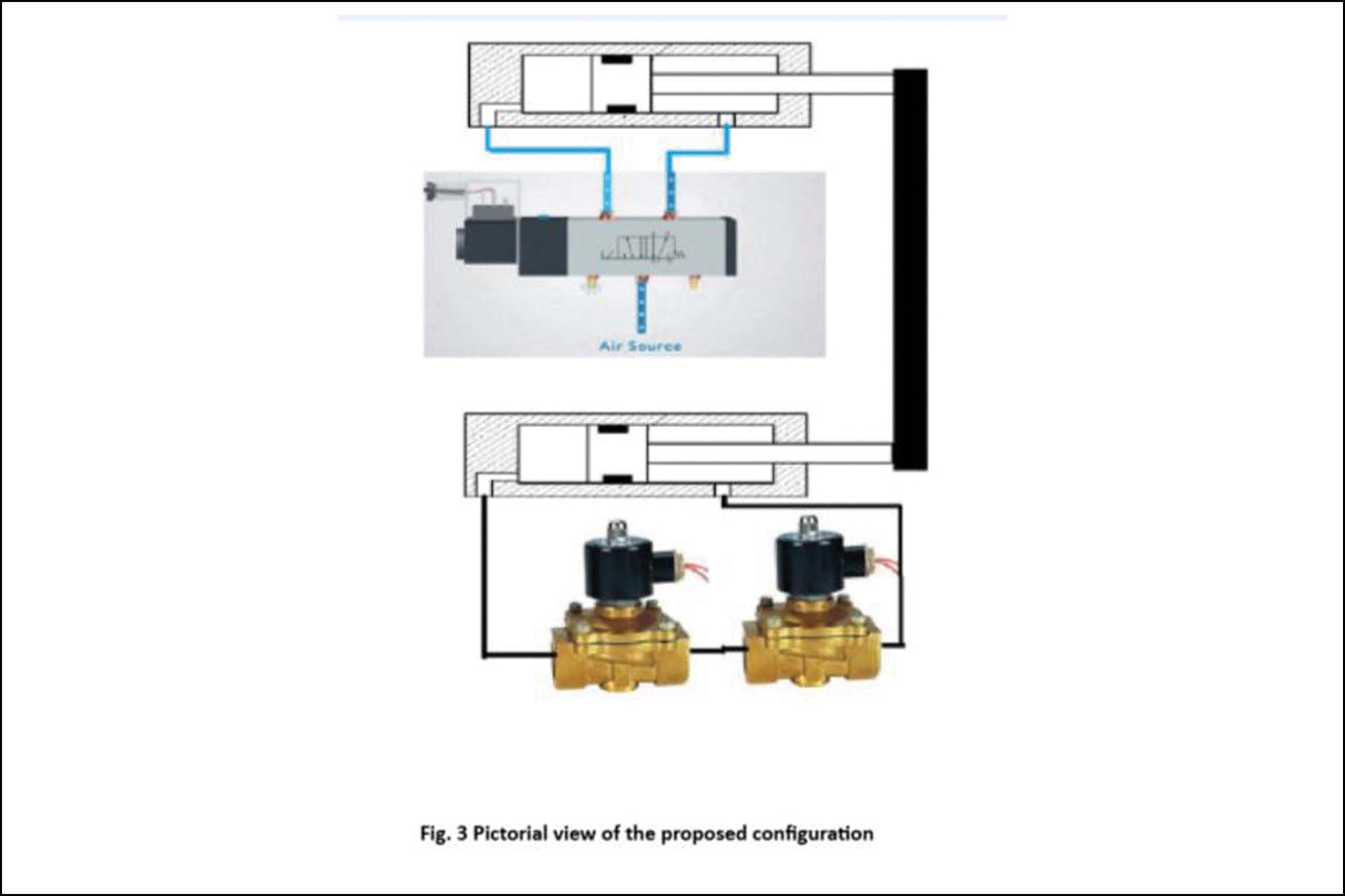
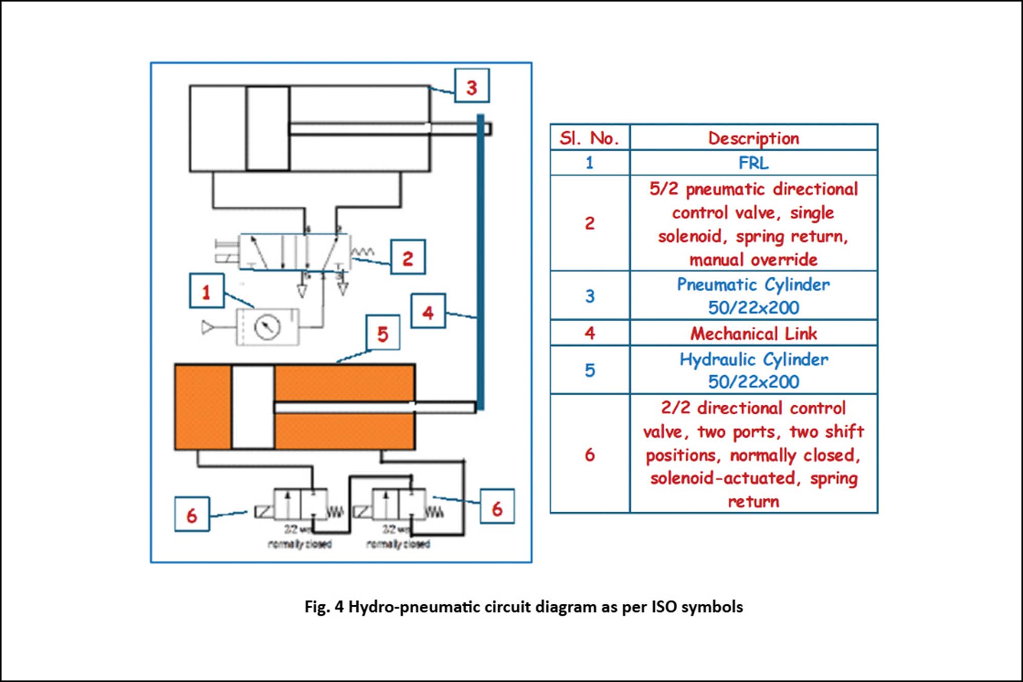
The innovative configuration proposed here includes a double-acting pneumatic cylinder (Φ 50 mm, stroke 200 mm) operated by a 5/2 directional control valve with a single solenoid, spring return, and manual override. The piston rod is mechanically coupled with a double-acting hydraulic cylinder, controlled by two 2/2 directional control valves, which are normally closed, solenoid-actuated, and spring return. Figures 3 and 4 illustrate the pictorial view and the hydro-pneumatic circuit diagram, respectively.
In this configuration, the pneumatic cylinder provides the primary driving force, while the hydraulic cylinder offers precise control over the position of the piston. By controlling the oil flow within the hydraulic cylinder, we can achieve positioning without complex and expensive sensors. The 5/2 pneumatic directional control valve (DCV) governs the movement of the pneumatic cylinder. When the solenoid is energised, the DCV shifts, allowing air to flow into the cylinder and move the piston.
The hydraulic cylinder, in parallel with the pneumatic cylinder, controls the position of the piston rod using two 2/2 DCVs. These valves are normally closed and open when energised, allowing oil to flow and control the piston’s position.
Experimental investigations
A test setup was assembled to validate the feasibility of the proposed concept. The setup included an air supply and a completely oil-filled hydraulic cylinder. The home position for the cylinder was set at mid-stroke (100 mm), and a scale arrangement was used to monitor the position. Tests were conducted at operating pressure ranging from 1.5 to 4 bar in 0.5 bar increments. The procedure involved:
Energising the 5/2 DCV to enable forward motion.
- Recording the initial rod end position.
- Energising the 2/2 DCVs for 1 second.
- Recording the new rod end position.
- De-energising the 5/2 DCV to enable return motion.
- Repeat the process ten times for each pressure setting.
These tests aimed to determine the positioning accuracy and repeatability of the system under various operating pressures. By recording the positions before and after each test, we could assess the system’s performance and identify areas for improvement.
Results and discussions
The preliminary test setup relied on manual timing and solenoid switching. Future improvements include incorporating timer circuits, automatic solenoid drivers, and displacement sensors for more accurate measurements.
The hydraulic cylinder used was sized similarly to the pneumatic cylinder. Return travel distances were observed to be shorter than forward due to increased flow resistance during the return stroke. A smaller area ratio (Φ = 1.06) for the hydraulic cylinder could improve performance.
Initially, a single 2/2 DCV was used in the bypass circuit, but increased flow resistance during the return stroke lifted the poppet off its seat, reducing effectiveness. This issue was mitigated by using two 2/2 DCVs.
At a supply pressure of 4 bar, the forward and return strokes were nearly 2.5 times those at 1.5 bar for a 1-second operation. Continuous piston movement in both directions in steps, rather than retraction after forward movement, could enable multiple intermediate stops.
Detailed observations and improvements
Manual to Automated Control: Manual timing and switching were employed in the preliminary setup. Automating this process with timer circuits and solenoid drivers will enhance precision and repeatability. Automating the control process can help achieve more consistent results and reduce the likelihood of human error affecting the measurements.
Measurement Accuracy: Displacement measurement in the initial tests was done visually using a steel scale. Integrating displacement sensors with data recording capabilities will provide more accurate and reliable data. These sensors can offer real-time feedback on the position of the piston, allowing for more precise control and adjustments.
Hydraulic Cylinder Optimisation: The current hydraulic cylinder configuration shows that return travel distances are shorter due to increased flow resistance. Optimising the hydraulic cylinder’s dimensions and configuration, such as using a 50/12 DAC with an area ratio of Φ = 1.06, could improve performance. Adjusting the cylinder’s size and shape can help balance the forces and achieve more uniform travel distances.
Enhanced Bypass Circuit: A single 2/2 DCV in the bypass circuit was initially ineffective during the return stroke due to flow resistance. The current setup uses two 2/2 DCVs, but further optimisation of the bypass circuit and sealing could enhance performance. Ensuring the bypass circuit can handle the required flow rates and pressures without excessive resistance is crucial for maintaining precise control.
Pressure Variation Effects: Tests showed that the forward and return strokes lengthened as supply pressure increased, indicating that pressure significantly affects performance. Understanding this relationship can help fine-tune the system for various applications. By analysing the effects of pressure variations, we can develop more effective strategies for achieving precise control.
Material Considerations: Copper, being ten times more expensive than steel, is a significant cost factor in motor production. Approximately 800 grams of copper are used per kW of a motor, impacting the overall cost. The lowest cost of a servo joint with a harmonic gearbox is about 1.2 Lacs per kW. These material considerations must be factored into the design and cost analysis of the system to ensure economic feasibility.
Future implications
The immediate application of pneumatic systems combined with hydraulic integration presents promising future implications:
Advanced robotics: The precise control achieved through this hybrid system can enhance the capabilities of industrial robots. Robots with this technology can perform delicate and complex tasks, opening new possibilities in manufacturing, healthcare, and service industries.
Smart manufacturing: Integrating sensors and IoT connectivity into pneumatic systems will facilitate the development of smart factories. These factories can monitor and adjust operations in real-time, improving efficiency, reducing downtime, and enabling predictive maintenance. By leveraging data analytics and real-time monitoring, we can optimise manufacturing processes and achieve higher levels of efficiency. Energy efficiency: We can save energy by optimising pneumatic systems with hydraulic integration. This is particularly important in industries where energy consumption is a major concern. The ability to precisely control airflow and pressure reduces waste and improves overall system efficiency. Implementing energy-efficient technologies can also contribute to sustainability goals and reduce operational costs.
Customisation and Flexibility: The ability to design and create customised solutions is advantageous. Industries with unique requirements can benefit from tailor-made systems that meet their needs, enhancing productivity and reducing costs. Customisation allows flexibility and adaptability, enabling us to respond to changing demands and challenges.
Safety and Reliability: Enhanced control systems improve the safety and reliability of pneumatic and hydraulic applications. In aerospace, automotive, and healthcare sectors, these improvements can prevent accidents, reduce failures, and ensure consistent performance. Improving safety and reliability is essential for maintaining high standards and meeting regulatory requirements.
Global Competitiveness: For manufacturers, adopting these advanced control systems can provide a competitive edge in the global market. Companies can attract new customers and expand their market reach by offering high-precision, energy-efficient, and customisable solutions. Staying ahead of technological advancements and market trends is crucial for maintaining a competitive position.
Conclusion
Integrating hydraulic solutions into pneumatic systems represents a significant advancement in achieving precise control in various applications. Hydax Pvt Ltd’s innovative approach leverages the strengths of both technologies to overcome the challenges posed by air compressibility and friction forces. Their research demonstrates that a hybrid system can provide a costeffective, reliable, and precise control solution.
The future of pneumatic systems lies in smart integration, where sensors, data analytics, and IoT connectivity enhance performance and efficiency. As HYDAX continue to refine and optimise these systems, significant advancements in robotics, manufacturing, energy efficiency, and safety will be witnessed.
Cookie Consent
We use cookies to personalize your experience. By continuing to visit this website you agree to our Terms & Conditions, Privacy Policy and Cookie Policy.
