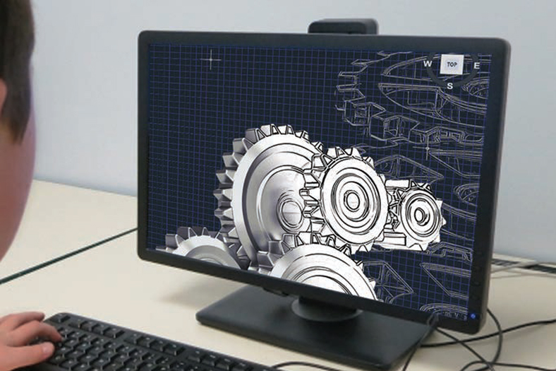
CAD/CAM : Technical geometry of manufacturing
By OEM Update Editorial January 11, 2019 3:18 pm IST
CAM programming is being used in manufacturing from last 15 to 20 years and is now very important aspect of manufacturing. Here, is a technical analysis on integrating CAD/CAM solution in manufacturing process.
Major companies have shifted from manual lath machines to automatic CNC and VMC machines. CAD/CAM has improved accuracy of manufacturing and improved quality. Due to less manual interventions combines, CAD and CAM program with a CNC or VMC machine can improve productivity by more than 50 per cent with better quality and less manpower.
Using an integrated CAD/CAM solution in manufacturing process
An integrated CAD/CAM solution has great benefits, especially for medium, small and micro industries, involved in any kind of CNC manufacturing. Typically, most MSMEs are suppliers to either tier1 or OEMs, across different industries. These MSMEs are also not usually originators of product design. They also employ teams who multi-task across processes. Therefore, Vineet Seth, Managing Director – South Asia & Middle East, Mastercam India, point out the need to have the ability to do the following, quickly and efficiently:
• Read in CAD data from various formats, including native file formats
• Verify that the imported data is in order. That there are no missing surfaces, features, or overlaps etc.,
• Quickly patch up any missing surfaces, features, overlaps, etc., using the Integrated CAD/CAM system
• Make minor modifications, if required, to help with workholding, fixturing, simple feature changes and machining.
• Be able to program a part across available machinery, using the same CAD/CAM interface, for operations in turning, milling, multi-axis machining and wire EDM, for example.
• Quickly be able to modify and apply changes to the part geometry and update associated toolpaths
• Communicate manufacturing intent through a common standard shop document – the NC process sheet
Vineet confirms, all of the above helps companies keep their downtime to a minimum and helps them save a lot of money, by ensuring that their machines are running continually, without a break in the process due to complications arising out of a non-integrated CAD/CAM system or awaiting data from the originators.
The quick and easy part setup in an Integrated CAD/CAM system, also allows for more accurate cost and time estimations, for pilot parts.
Prabhu Mishra, Regional Head India, Southern region, Angel India Cad Cam Pvt Ltd says, “We are into raw fibre laser, so without CAD/CAM we cannot process with any single design. So, when it comes to the material cost of thing, we are saving at least 30 to 40 per cent by using CAD/CAM. When it comes to the designing part, so 3D is the most comfortable technology and we are using it.”
Latest trends in the CAD technology to aiding the manufacturing process
CAD for CAM is a field that is gathering a lot of pace. With Agile systems in place, a lot of organisations are opting for direct design methodologies, unlike the traditional system of constraint modelling.
Getting a part file from an outside source can pose unique challenges. You might need to repair a surface, cap an area, create an electrode, or just make sure your fixtures are represented on the part. From robust surface creation and editing to ‘push-pull’ solid model editing, CAD for CAM gives you the tools to bring a part, from the designer’s desk to your machine, fast. So, Vineet shares some of the capabilities of CAD for CAM as:
• Easy geometry modelling and editing
• Create parametric and NURBS surfaces using loft, ruled, revolved, swept, draft, and offset creation methods
• Create splines on surfaces using a variety of functions including surface projections, surface intersections, edge curves, slicing curves, and parting lines
• Region chaining explicitly defines the area for a 2D dynamic milling toolpath by simply selecting the face to be machined and face to be avoided, while treating the selections as complete machining chains
• Analyse surface curvature to identify undercuts and minimum radius
• Quickly modify parameters such as line length and arc radius after creation
• 64-bit support lets you take full advantage of your 64-bit hardware and operating system
Align to Face: This is to control orientation when mating solid models. This is useful for aligning inserts to holders when creating 3D tools. Align to Face allows you to work in three modes, coincident, perpendicular, and parallel.
Coincident allows you to copy or move a solid by mating a face on the solid to another solid’s face. Parallel and perpendicular require you to select a linear edge on the solid body that is being moved and on the target solid body. When you select a linear edge on the solid body that is being moved, Mastercam aligns the X axis of the gnomon to that edge. When you select an edge on the target body, Mastercam aligns the X axis of the solid being moved to be perpendicular or parallel to that edge.
Align to Face also supports mating cylindrical faces. After you select the faces, Align to Face rotates each body into position and mates each face at its center. It rotates the object into position, if the bodies are not in same plane or of the same radius.
Align to Z: It aligns a solid body that is used for a turning operation to a new WCS or an existing construction plane along the Z axis. This lets you orient the body so that is ready to machine.
Align to Plane: It aligns a solid body to a new WCS or an existing construction plane. You can align an edge of the solid to the X axis of the plane or WCS, and a selected point on the solid to the origin of the WCS or plane.
Edit surface: It allows you to make edits to existing surfaces. You can modify the tangencies and magnitudes of the curve at nodes points, or edit tangencies at the vectors of control points. You can also add or remove node points and isocurves to increase your editing control and to make finer adjustments.
Edit Surface includes tools that allow you to assess and analyse the surface you are working on. You can add or remove the visibility of flow lines along the U or V axes. Curvature combs represent the curvature of the surface and display curvature continuity or discontinuity.
In addition to the above, Dynamic Push-Pull of surfaces and feature faces, hole axis alignments, disassemble feature, join entities and curves, on screen controls etc. are some of the other latest trending features in an Integrated CAD/CAM system.
CAD/CAM helps companies to keep their downtime to a minimum.
Vineet Seth, Managing Director – South Asia & Middle East, Mastercam India
When it comes to the material cost of thing, we are saving at least 30 to 40 per cent by using CAD/CAM
Prabhu Mishra, Regional Head India Southern region, Angel India Cad Cam Pvt Ltd
Additive manufacturing is one of the technologies which are evolving very fast
Girish Modi, Director, 3 M software solution
Cookie Consent
We use cookies to personalize your experience. By continuing to visit this website you agree to our Terms & Conditions, Privacy Policy and Cookie Policy.
